Building computers in Build A Boat For Treasure
A complete, game-accurate guide to the Logic Blocks Update (20 June 2026): the new Gate, Display, Sensor and Delay blocks, the calculated-state wiring model, and how to climb from a single logic gate to a working 4-bit computer inside the game.
How to read this guide
▼This is a builder's manual, not a hype video. The goal is that every technique here actually works in game, so accuracy is treated as the whole point.
The Logic Blocks Update is new (20 June 2026), and the wiki is still catching up to it: some block pages still show pre-update text, and a couple still call the new blocks "testing only" even though the changelog says they shipped. To handle that honestly, every non-obvious claim carries a confidence tag:
Where the game leaves something genuinely unknown (how fast signals propagate, what the Sensor Block really does), this guide says so plainly instead of guessing. The big lesson up front: the things the game does not document are exactly the things that make memory circuits tricky, and the fix is almost always the Delay Block.
Quick start: 10 things to know
▼If you read nothing else, read these. Each links to the full section.
- Wires now do OR by default. A block is ON if any connected block is ON. This is the single biggest change and the cause of most "why is it always on" confusion. [2] High
- To get real logic, put a Gate in the middle. Never wire two inputs straight into one output unless you actually want OR. [8]
- The Gate block does AND, OR, XOR, plus a NOT flag that turns them into NAND, NOR, XNOR. It glows green when its output is HIGH, which is your free signal tester. [5] High
- There is no NOT block. Build an inverter from a NOR gate fed by a single input. [6] High
- XOR means "odd number of inputs HIGH", not "exactly one." For 2 inputs this is normal XOR; with 3+ inputs it is a parity gate. [5] High
- A Switch is your logic "1". It latches on; leave one toggled on for a constant HIGH. A Button is momentary (only HIGH while held). [6]
- The Delay Block (0.05 to 10 s) is the only reliable timing tool. Build every clock, pulse, and memory cell around it. [7] High
- Old builds load with "Legacy" ON. If your new wiring on an old switch/button/delay does nothing, turn Legacy OFF. [4] High
- Test in the plot without launching: turn Anchor OFF and watch the gates go green. Launching un-anchors everything. [12]
- A 4-bit adding calculator is genuinely buildable today for under ~1000 gold of blocks. A full CPU is possible in principle but leans on undocumented timing, so build and test in stages. [11]
What the update changed
▼The Logic Blocks Update (also called the Logic Update or Logic Gates Update) went live on 20 June 2026. It did two things: it added a set of logic blocks, and it rebuilt how every wired block decides its on/off state.
New blocks (all released 20 June 2026)
- Gate - the logic-gate block (AND / OR / XOR, invertible to NAND / NOR / XNOR). High
- Display Block - copies the colour of connected blocks; tile many of them to make screens. High
- Sensor Block - a detection block (proximity / weight / players, per community use). Function is barely documented. Low
- Remote Controller - wireless / remote triggering. Function is barely documented. Low
System changes
- A new "calculated state" signal model replaced the old direct-toggle model. This is the heart of the update. See section 2. High
- A new "Legacy" property on Switch, Button and Delay blocks restores the old behaviour. Old saves load with it ON. High
- Binding Tool upgrades: a "Show visuals" toggle and selection-only highlighting (only the selected block's wires light up). An "unbind all" button is reported but not fully confirmed. High
- Input delay removed for light bulbs, jet turbines, thrusters, shield generators and glue blocks. High
- Blocks keep working through respawn, and far more block states now save (16 block types, including switches, buttons, delays, seats, motors and more). High
- Property Tool gained custom numeric values; servo angle max went 90° to 180°; piston speed max went 10 to 600 (600 is instant). High
- Lag safeguards were added against rapidly activating large bundles of functional blocks, which matters for big fast circuits. Medium
The signal model: calculated state
▼Understand this one idea and the rest of the guide falls into place.
Before the update, an input block (a switch, say) directly toggled each block it was wired to. After the update, a block's on/off state is calculated from the states of every block connected to it. The default combining rule is OR.
The one consequence that matters
A bare wire from an input to an output is already an OR of everything feeding that output. So:
What travels on a wire
- Signals are HIGH / LOW (on/off). The game never literally says "boolean," but nothing analog is documented to travel on a normal wire. Medium
- The one exception is colour, which is carried specifically to the Display Block. See section 10. High
Timing: the honest gap
The game does not document whether all connected blocks recalculate at the same instant or in some order, and there is no documented per-gate delay.
Fan-in and fan-out
- Fan-out (one source to many targets): supported. Each target simply sees your source. Clean.
- Fan-in (many sources to one target): supported, but the target computes OR of them by default. Insert a Gate to change the rule.
- No maximum number of connections is documented, but the new lag safeguards may throttle very wide or very fast bundles. Low
The two tools you wire with
▼Logic in BABFT is built with two tools: the Binding Tool connects blocks, and the Property Tool sets what each block does.
Binding Tool (also called the Bind Tool)
It "links input blocks to output blocks. Input blocks produce a signal when triggered (a Button). Output blocks perform a function when they receive a signal." You can select input-then-output or output-then-input; the bind is the same either way. High
While you hold the tool, blocks are outlined by role:
- Purple = an input block
- Yellow = an output block
- Orange = a repeater (the Delay Block), which can both trigger and be triggered
An existing bind shows as a wavy purple-yellow line whose animation flows from input to output, so you can always tell which end is which. New in this update: a "Show visuals" toggle to hide the clutter, and selection-only highlighting so only the wires of the block you point at light up. High
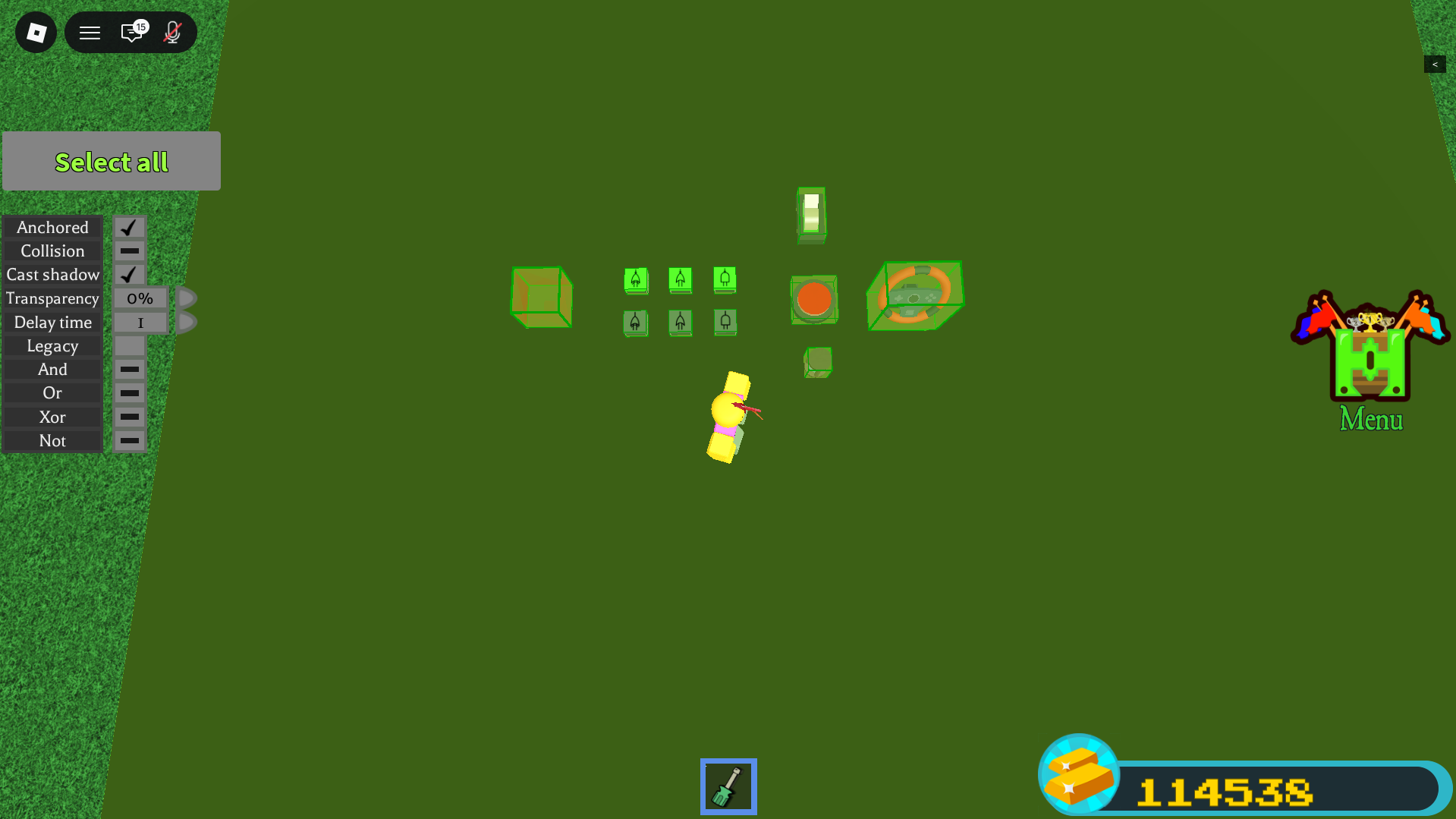
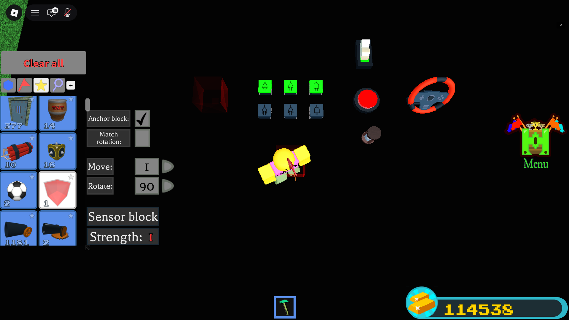
Property Tool
Point it at a block to open the panel from the screenshot above. It sets the gate mode (And / Or / Xor), the Not invert, the Delay time, the additive flag, Legacy, and the four properties every logic block shares:
| Universal property | Options | Default |
|---|---|---|
| Anchor | on / off | tied to build anchor |
| Collision | on / off | On |
| Cast shadow | on / off | On |
| Transparency | 0% / 25% / 50% / 100% | 0% |
Block reference
▼Everything you can wire, with the facts that matter for circuits. Costs are from the individual block pages (the in-game shop tables still lag the update).
Gate New High
Shop text: "Uses boolean algebra to enable the creation of electronic circuits." This is the block that overrides the OR default and lets you build real logic.
- One Gate does one of AND, OR, XOR, chosen in the Property Tool, and the Not flag inverts it to NAND, NOR, XNOR. It outputs the chosen operation over all its bound inputs.
- AND = all inputs HIGH. OR = at least one HIGH. XOR = an odd number HIGH (true parity over however many inputs). Full truth tables in section 5.
- It turns green when its output is HIGH. This is your built-in tester for "is this signal on right now."
- Gate outputs can be bound onward, so gates chain into bigger circuits.
- Painting a Gate lets it set the colour of a Display Block it feeds.
 Gate, output HIGH (green)
 Gate, idle (LOW)
 Gate (other op)
 Gate (other op)
The plug-like symbol and its colour change with the gate's mode and state. The green vs blue background is the on/off look you will see in the build menu.
Display Block New High
"A functional block that copies the colour of connected blocks that turn on." One Display Block is one coloured cube; tile many to make a screen.
- Default mode: changes to the colour of its most recently activated input, and a one-time signal is enough, so it holds that colour. This makes it a free one-colour memory cell / status light.
- Additive mode: the colour becomes the sum of its colour inputs (two 100-red inputs give 200 red), capped at 255 per channel. Important catch: additive mode needs the inputs held HIGH to keep the colour. It also ignores any input that has Legacy ON.
- No pixel grid: screens are made by tiling many Display Blocks, each driven by its own painted Gate.
- An "Allow fast flashes" setting (off by default) caps colour changes at roughly 0.5 s; the wiki ties this to test servers, so live behaviour is unconfirmed. Medium
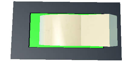 Output block, ON
 Output block, OFF
Delay Block High (not new, but central)
It "holds a received signal for a period of time, shown by its glass turning red, before forwarding it." This is the only reliable timing primitive in the game, so it shows up in every clock and memory circuit.
- Set the delay time in the Property Tool (custom decimals allowed). While holding, the glass turns red and it cannot be re-triggered, so it is a clean one-shot. Edges arriving faster than the delay are dropped.
- Delay Blocks can feed other Delay Blocks: chain them for a longer delay, or loop one back to itself for a repeating clock. Loops keep running after respawn.
- Gained the Legacy property in this update, and its state now saves.

Sensor Block New Low confidence on function
Listed among the four new logic blocks, but its wiki page is a stub: no documented detection range, target, or output type. Community video titles point to distance, weight and player detection (motion sensors, player trackers, auto-aim contraptions), but specifics are unverified.

Remote Controller New Low confidence on function
Also one of the four new blocks, also a stub page. Community use points to wireless / remote triggering (for example a remote-control missile). Channels, pairing and range are plausible but unverified. Treat its details as unknown until you test in game.
Classic input blocks
| Block | Behaviour | Cost | Use as |
|---|---|---|---|
| Switch | Latches: click on, click off; outputs continuously while on | 50 g each | held condition, mode select, constant HIGH (logic 1) |
| Button | Momentary: HIGH only while the mouse is held | 75 g each | pulses, triggers, clock ticks |
| Lever | Same as Switch, but unobtainable now | n/a | (use a Switch instead) |
 Button
 Button (painted)
 Steering / seat input
Classic output blocks affected by the update
- Light Bulb (60 g for 3): the standard signal-controlled light and the changelog's own example of calculated state. It is lit if any connected block is on. Input delay was removed; state now saves. To make it read one specific signal, bind only that source (or gate it).
- Seats (Car / Pilot): count as inputs in the Binding Tool; state now saves; not in the Legacy list.
- Doors, servos, pistons, thrusters, jet turbines, magnets, balloons, parachutes and more now save state and keep working through respawn. Servo angle and piston speed limits were raised (see section 1).
The Legacy property High
Changelog: "Added a new 'Legacy' property to switch blocks, button blocks, and delay blocks ... Past builds that include switch, button, or delay blocks will load with the 'legacy' property set to on. This is to preserve the functionality of old builds."
- Legacy ON = the old direct-toggle behaviour (the input directly flips the connected block, instead of feeding the OR-based calculated model).
- Old saves auto-load with Legacy ON; freshly placed blocks default to Legacy OFF (the new model).
- Scope: the changelog names three blocks (Switch, Button, Delay). The Property Tool page additionally lists Big Switch and Lever; that extension is documented but not independently confirmed. Medium
Names that do NOT exist
To save you searching: there is no "Detector" block (the detection block is the Sensor Block), no "Light" block (the toggleable light is the Light Bulb), and "Regen" is the build-menu reset function, not a wireable block. High
The build tools, for reference
 Property tool
 Paint
Paint Hammer
 Trowel
 Delete
Gates and truth tables
▼A logic gate takes one or more HIGH/LOW inputs and produces one HIGH/LOW output by a fixed rule. The BABFT Gate gives you three base rules (AND, OR, XOR) and a NOT flag that inverts any of them.
Interactive gate simulator
The lamp glows green for HIGH, exactly like the real Gate. Switch to XOR and turn on all three inputs to see the parity behaviour described below.
The six gate modes
| Mode | Property setting | Output is HIGH when |
|---|---|---|
| AND | And on, Not off | all inputs HIGH |
| OR | Or on, Not off | at least one input HIGH |
| XOR | Xor on, Not off | an odd number of inputs HIGH |
| NAND | And on, Not on | not all HIGH |
| NOR | Or on, Not on | all inputs LOW |
| XNOR | Xor on, Not on | an even number of inputs HIGH (including zero) |
Two-input truth tables
| A | B | Y |
|---|---|---|
| 0 | 0 | 0 |
| 0 | 1 | 0 |
| 1 | 0 | 0 |
| 1 | 1 | 1 |
| A | B | Y |
|---|---|---|
| 0 | 0 | 0 |
| 0 | 1 | 1 |
| 1 | 0 | 1 |
| 1 | 1 | 1 |
| A | B | Y |
|---|---|---|
| 0 | 0 | 0 |
| 0 | 1 | 1 |
| 1 | 0 | 1 |
| 1 | 1 | 0 |
| A | B | Y |
|---|---|---|
| 0 | 0 | 1 |
| 0 | 1 | 1 |
| 1 | 0 | 1 |
| 1 | 1 | 0 |
| A | B | Y |
|---|---|---|
| 0 | 0 | 1 |
| 0 | 1 | 0 |
| 1 | 0 | 0 |
| 1 | 1 | 0 |
| A | B | Y |
|---|---|---|
| 0 | 0 | 1 |
| 0 | 1 | 0 |
| 1 | 0 | 0 |
| 1 | 1 | 1 |
Multi-input XOR is parity (the #1 surprise)
The Gate works on all its bound inputs, not just two. For AND and OR that is intuitive. For XOR it means "an odd number of inputs are HIGH", which is not the same as "exactly one."
| A | B | C | XOR |
|---|---|---|---|
| 0 | 0 | 0 | 0 |
| 0 | 0 | 1 | 1 |
| 0 | 1 | 0 | 1 |
| 0 | 1 | 1 | 0 |
| 1 | 0 | 0 | 1 |
| 1 | 0 | 1 | 0 |
| 1 | 1 | 0 | 0 |
| 1 | 1 | 1 | 1 |
A ⊕ B ⊕ Cin, which is the full-adder sum. So this "surprise" is a gift for adders.Setting a gate, step by step
- Place the Gate with the Building Tool (64 gold for 4).
- Equip the Property Tool and click the Gate to open its panel.
- Turn on exactly one of And / Or / Xor.
- For the inverted version, also turn on Not (AND becomes NAND, OR becomes NOR, XOR becomes XNOR).
- Equip the Binding Tool and bind your input block(s) into the Gate. For multiple inputs, click each one (there is no drag box).
- Bind the Gate's output onward to the next block.
- Test: the Gate glows green when its output is HIGH.
Primitives: the parts every circuit reuses
▼Six small building blocks come up again and again. They all use confirmed mechanics.
Constant HIGH (logic 1)
There is no power or VCC block. The standard constant HIGH is a Switch left toggled on: it outputs continuously and its state saves. Leave its Legacy OFF so it feeds the calculated model. A Button will not work for this, because it is only HIGH while held.
NOT / inverter (no NOT block exists)
From the Gate page: "To replicate a NOT operation, XOR or NAND can be paired with the desired input and a constant high input. Alternatively, a NOR gate bound exclusively to the desired input can be used." Two recipes:
XOR(x, 1) = NOT x and NAND(x, 1) = NOT x. Use this when a constant-high line already runs nearby. Set the gate to XOR (or AND+Not) and bind x plus a constant-HIGH Switch.Buffer / wire (pass-through)
- If exactly one block feeds an output, the output simply equals that input. One bind is a faithful wire.
- For a clean isolated stage with a free green probe, route through an OR-mode Gate fed by one input (OR of one input = pass-through).
- For a time-shifted copy, route through a Delay Block (remember it is a one-shot while holding).
Pulse vs hold
| Input | Output shape | Use it to |
|---|---|---|
| Button | momentary pulse (HIGH while held) | fire a one-shot, clock a chain, kick a latch |
| Switch | held level (until clicked again) | enable lines, mode select, constant HIGH |
Fan-out (one source, many targets)
Equip the Binding Tool, select the source, then click each target in turn. There is no drag-select, so click them individually; verify with the selection-only highlight. No maximum is documented, but the lag safeguards may throttle very wide or fast fan-outs. Low
Reading state (three ways)
- Gate green-glow (free, in-line): any Gate turns green when HIGH. Drop a one-input OR-buffer Gate as a probe anywhere.
- Light Bulb: a binary on/off indicator. Remember it ORs all its inputs, so gate it if you want one specific line.
- Display Block: a colour readout and a one-colour memory in its default mode.
Wiring and timing hazards
▼This is the analytical heart of building reliable circuits in BABFT. The calculated-state model is simple, but it has sharp edges. Know these five before you build memory.
1. The simultaneity hazard (the big one)
Real-world memory latches work because each gate has a tiny, definite delay, so feedback arrives a beat after the cause. BABFT documents no such per-gate delay. If states recalculate all at once, a cross-coupled latch can fail to settle or oscillate.
2. The OR-default "always on" hazard
Because the default is OR, binding two things to one output gives "on if either is on." This silently breaks hold logic: a feedback line ORed onto an output keeps it stuck high. Fix it by routing through an explicit Gate, or by setting Legacy.
3. The forbidden-state hazard
A NOR SR latch with both Set and Reset high is undefined, and without a guaranteed gate delay there is no defined way to resolve the race. Never drive Set and Reset high together. The gated D latch (section 9) prevents this by construction.
4. The Delay re-trigger deadtime
"During this hold state, the Delay cannot be activated again." Edges arriving faster than the delay time are dropped. Size the delay to your fastest event; use 0.05 s for minimum deadtime and chain delays only for longer windows.
5. The additive-Display constant-signal trap
Additive mode needs its inputs held HIGH to keep the colour. A pulsed or latched signal that goes low loses the colour. For memory or status cells, use the Display's default mode, which latches the last colour from a one-time signal (a free 1-bit colour memory).
Combinational circuits
▼Combinational means "output depends only on the current inputs," with no memory. These are the safest circuits to build first, because you can watch them work in the plot with anchor off.
Half adder
Adds two bits: Sum = A ⊕ B, Carry = A · B. One XOR Gate and one AND Gate.
| A | B | Sum | Carry |
|---|---|---|---|
| 0 | 0 | 0 | 0 |
| 0 | 1 | 1 | 0 |
| 1 | 0 | 1 | 0 |
| 1 | 1 | 0 | 1 |
Blocks: 2 Switches (A, B), 1 XOR Gate, 1 AND Gate, 2 Light Bulbs. Wire A and B into both Gates, then each Gate to its lamp. That is 2 Gates per bit.
Full adder
Adds three bits (A, B, and a carry-in): Sum = A ⊕ B ⊕ Cin, Cout = (A · B) + (Cin · (A ⊕ B)). The BABFT shortcut is that the Sum is a single 3-input XOR Gate (parity of 3).
| A | B | Cin | Sum | Cout |
|---|---|---|---|---|
| 0 | 0 | 0 | 0 | 0 |
| 0 | 0 | 1 | 1 | 0 |
| 0 | 1 | 0 | 1 | 0 |
| 0 | 1 | 1 | 0 | 1 |
| 1 | 0 | 0 | 1 | 0 |
| 1 | 0 | 1 | 0 | 1 |
| 1 | 1 | 0 | 0 | 1 |
| 1 | 1 | 1 | 1 | 1 |
5 Gates per bit: G_S = XOR(A,B,Cin) (Sum); HX = XOR(A,B) (helper); G_ab = AND(A,B); G_cx = AND(Cin,HX); G_cout = OR(G_ab,G_cx).
4-bit ripple-carry adder
Chain four adders, feeding each carry-out into the next carry-in. Bit 0 can be a half adder (carry-in is always 0) to save gates. The final carry-out is your overflow flag (result greater than 1111).
- Gate count: bit 0 half adder (2) + three full adders (15) = 17 Gates, about 5 packs (80 gold), plus 8 Switches and 5 Light Bulbs.
- Timing note: ripple assumes the network settles to its steady value. Because propagation timing is undocumented, expect brief wrong lamps while it settles. If it bothers you, gate the readout behind a Delay. Assumed
Subtractors (two's complement)
Compute A - B as A + (NOT B) + 1. Reuse the ripple adder, but invert every B bit with a NOR-of-one Gate and force the bit-0 carry-in HIGH using your constant Switch. The final carry-out is "no borrow": C4=1 means A is greater than or equal to B; C4=0 means A is less than B (the result wrapped negative).
- Worked check: A=0101 (5), B=0011 (3). NOT B = 1100. 0101 + 1100 + 1 = 0010 (2), C4=1. Correct.
- Worked check: A=0011 (3), B=0101 (5). NOT B = 1010. 0011 + 1010 + 1 = 1110 (-2 in two's complement), C4=0 (borrow). Correct.
- Gate count: 4 full adders (20) + 4 invert NORs + 1 borrow-indicator NOR + 1 constant Switch = about 25 Gates.
Magnitude comparator
Per bit: EQ = A XNOR B, GT = A · (NOT B), LT = (NOT A) · B.
| A | B | GT | EQ | LT |
|---|---|---|---|---|
| 0 | 0 | 0 | 1 | 0 |
| 0 | 1 | 0 | 0 | 1 |
| 1 | 0 | 1 | 0 | 0 |
| 1 | 1 | 0 | 1 | 0 |
4-bit (most-significant-bit priority): per-bit equality eqi = Ai XNOR Bi; then EQ = eq3 · eq2 · eq1 · eq0 (one 4-input AND); GT ORs "this bit greater and all higher bits equal" terms; and the cheapest LT = NOR(GT, EQ).
Multiplexers, demultiplexers, decoder
- 2:1 MUX (pick D0 or D1 with S):
Out = (NOT S · D0) + (S · D1). Blocks: NOR-of-one(S), two ANDs, one OR. - 4:1 MUX: decode the two select bits into 4 minterms, AND each with its data, OR the four. About 11 Gates.
- 2:4 decoder (optionally with an enable E):
Y0 = E · NOT S1 · NOT S0, and so on for Y1..Y3. Two inverters plus four 3-input ANDs. This is the workhorse behind the 4:1 MUX and behind memory addressing.
Display and segment drivers
- Colour pixel: paint a Gate the pixel colour, drive its logic, and bind the painted Gate into a Display Block. When the Gate goes HIGH the Display copies and latches that colour (default mode). To change it, fire a differently painted Gate.
- 7-segment digit: there is no 7-seg block, so each segment is a Light Bulb or a painted Display pixel. Decode the number with a 2:4 decoder, then each segment is an OR of the decoder lines for which that segment is on.
- Pixel screen: tile an N x M grid of Display Blocks, each with its own painted Gate. A 16 x 16 screen (256 pixels) is roughly 1,536 gold of Displays and is where lag starts to bite, so keep refresh modest.
Sequential circuits (memory and timing)
▼Sequential circuits remember. They need feedback, and BABFT's model fights feedback (the OR default makes things sticky, and there is no documented gate delay). The practical answer is: build and test the combinational parts first, then add memory carefully, always with a Delay Block in the loop.
SR latch (cross-coupled NOR)
| S | R | Q next | meaning |
|---|---|---|---|
| 0 | 0 | Q | hold |
| 1 | 0 | 1 | set |
| 0 | 1 | 0 | reset |
| 1 | 1 | 0 | forbidden |
Q = NOR(R, Q̅) and Q̅ = NOR(S, Q). So R feeds the gate that produces Q (call it G1), and S feeds the gate that produces Q̅ (G2). If you read Q off the S-fed gate, Set and Reset look swapped and the latch seems broken.Blocks: 2 Gates set to NOR (Or on, Not on), Set and Reset inputs (Buttons), and Light Bulbs on Q and Q̅. There is also a NAND version (active-low), but because BABFT's default is active-high, the NOR version is friendlier; prefer it unless you specifically want active-low control.
The canonical robust latch (use this one)
A hazard-resistant set-dominant memory cell. Build every memory element this way.
- G1 = NOR (produces Q), G2 = NOR (produces Q̅).
- Bind RESET into G1.
- Bind G2 through a Delay (0.05 s) into G1 (the ordered Q̅ feedback).
- Bind SET into G2.
- Bind G1 through a Delay (0.05 s) into G2 (the ordered Q feedback).
- Bind G1 into a Light Bulb (Q).
- Test with anchor off: SET lights Q and it stays; RESET clears it and it stays; mashing SET is harmless; never press SET and RESET together.
The two small Delays turn the ambiguous simultaneous recompute into a defined "set, then settle" sequence. That is the difference between a latch that works and one that races.
Gated D latch (no forbidden state)
One data input D and an enable E. When E is high it is transparent (Q follows D); when E is low it holds. Built from the SR core with S = D · E and R = (NOT D) · E, so S and R can never both be high.
| E | D | Q next |
|---|---|---|
| 0 | x | Q (hold) |
| 1 | 0 | 0 |
| 1 | 1 | 1 |
Blocks: NOT_D = NOR-of-one(D); S_gate = AND(D,E); R_gate = AND(NOT_D,E); plus the NOR SR core (with the Delay feedback). Hazard: it is transparent the whole time E is high, so for capture at a single instant use the edge-triggered flip-flop below.
The edge detector (the most useful sequential trick)
Pulse = X AND (NOT delayed X). The instant X rises, X is 1 but its delayed copy is still 0, so the AND is 1 for the length of the delay; then the delayed copy catches up and the pulse ends. Pulse width is about the delay time.
This converts the always-on level model into discrete events, which is what flip-flops and counters need.
Edge-triggered D flip-flop
Put the edge detector on the clock line and feed its pulse as the Enable of a gated D latch. The latch is transparent only during the brief pulse at each clock edge, so Q captures D at that instant and holds otherwise. This is the building block of registers and counters.
Button debouncing
BABFT inputs are software toggles, so they probably do not physically bounce, but you often want to collapse rapid mashing into one clean event. Easiest: bind Button into a Delay (0.2 to 0.5 s) and take the output. The Delay's re-trigger lockout swallows extra presses during the window and forwards one clean pulse.
Memory, registers and screens
▼1-bit memory cells
- Easiest and confirmed: a Display Block in default mode. A one-time signal latches its colour and it holds with no feedback. Perfect as an output latch, status light, or screen pixel. Limitation: there is no documented way to read its stored colour back out as a wire signal, so it cannot be the storage element that feeds an ALU.
- Re-readable storage: the robust NOR SR latch or gated D latch from section 9. This is the kind you can wire back into logic.
D flip-flop and n-bit register
A register is N D flip-flops sharing one clock. Budget roughly 5 Gates plus 1 Delay per bit, so an 8-bit register is about 80 Gates plus delays (around 1,280 gold). Multi-bind the single clock to every bit's enable; if you see skew, route the clock through a Delay to each bank. A wide, fast-clocked register is exactly the pattern the lag safeguards may throttle, so keep clocks slow.
Counters and the clock
- Clock / oscillator: Delay into NOR-of-one (inverter) and back into the Delay, a ring oscillator. Period is roughly 2 times the delay time, so 0.5 s delay gives about a 1 Hz blink. Kick it once with a Button to start it; it keeps running through respawn. Driving a Display hits the ~0.5 s flash cap, so drive a Light Bulb for fast clocks. Assumed on exact period; calibrate in plot.
- Ripple counter: chain T flip-flops, each stage clocked by the previous stage's output; stage i toggles at half the rate of i-1, giving a binary count.
- Synchronous counter: all flip-flops share one clock, with an AND chain deciding which bits toggle (T1=Q0, T2=Q0·Q1, and so on). No ripple skew.
Small addressable memory (a tiny RAM)
A 4-word by 1-bit RAM shows the pattern. The addressing is fully combinational and safe; only the storage latch carries the feedback caveat.
- 2-to-4 address decoder: one Select line goes high for each address. Test it lighting Light Bulbs first, before trusting the latches.
- Per cell: a write gate
AND(Sel_k, WriteEnable)drives that cell's latch (data is a shared Data-in line); a read gateAND(Sel_k, ReadEnable, Q)contributes to the read bus. - The read bus is free: bind every cell's read output to one Data-out block, and the OR default combines them. Only the selected cell drives high. The OR default that fights you elsewhere is exactly what a wired-OR read bus wants.
Driving a Display screen or number readout
- Binary readout (cheapest): one Display per register bit, each via a painted Gate. A row of them reads the register in binary.
- 7-segment decimal: 7 Displays as segments, driven by a binary-to-7-segment decoder built from gates. Tile digits for multi-digit numbers.
- Animation: feed a counter into the screen's scan logic, clocked by a Delay loop. Keep the period at or above ~0.5 s if "Allow fast flashes" is off.
Worked build: from a gate to a computer
▼This pulls everything together. We build a real, testable 4-bit binary calculator step by step, then explain how it extends toward a full computer.
The conceptual machine
A minimal computer is: inputs feed an ALU (the maths unit), results land in registers on a shared bus, a clock paces everything, and a little control logic selects the operation.
- ALU: per-bit add/subtract (section 8) plus AND/OR, with a multiplexer choosing which result to keep. The op-select mux is the heavy part: roughly 3 gates per bit per option, so a 4-bit selectable ALU is 50+ gates on its own.
- Registers on a bus: the Display latch is the cheapest visible bit (write-and-hold only); a true gated latch is needed for re-readable storage. The bus is wired-OR with one enable-AND per driver.
- Clock: a self-feeding Delay loop. Do not run it faster than the logic can settle; start around 1 s.
- Control: latching Switches pick the operation; a compute Button (or the clock) triggers a latch after a Delay "settle beat" so registers capture only after the gates have settled.
Worked build: a 4-bit binary calculator (ADD)
Two 4-bit numbers A and B on Switches, a 4-bit ripple adder, the result on 4 Light Bulbs plus a carry light. Build one bit, prove it, then ripple. This is fully buildable today from confirmed mechanics.
| Item | Qty | Pack price | Cost |
|---|---|---|---|
| Switch (8 input bits) | 8 | 50 g each | 400 g |
| Gate (adder core) | ~17 | 64 g / 4 | ~272-320 g |
| Light Bulb (4 results + carry) | 5 | 60 g / 3 | 120 g |
| Delay Block (optional settle beat) | 2 | 50 g / 2 | 50 g |
| Display Block (optional readout) | 0-4 | 96 g / 16 | 0-96 g |
| Binding Tool (one-time) | 1 | 2000 g | 2000 g |
Working total (excluding the one-time Binding Tool): about 840-940 gold. First-timers who still need the tool budget about 2,800-2,900 gold. A 16-to-25 gate build like this is well within normal play; the expensive, laggy stuff only starts with big Display screens.
Stage A: one bit (the checkpoint that teaches everything)
Place 2 Switches (A0, B0), 2 Gates (SUM0 = XOR, CARRY0 = AND), 2 Light Bulbs. Wire A0 and B0 into both Gates; SUM0 into the white lamp, CARRY0 into the red lamp.
| A0 | B0 | SUM0 green | CARRY0 green |
|---|---|---|---|
| off | off | no | no |
| on | off | yes | no |
| off | on | yes | no |
| on | on | no | yes |
Stage B: promote bit 0 to a reusable full-adder cell
Each cell is 5 Gates: SUMi = XOR(Ai,Bi,Cin), HXi = XOR(Ai,Bi), G1 = AND(Ai,Bi), G2 = AND(Cin,HXi), COUTi = OR(G1,G2). For bit 0 leave Cin unbound (it is 0), so it stays the simpler half adder. Test the cell standalone with a temporary Cin Switch against the full-adder table in section 8.
Stage C: ripple to 4 bits
Build cells for bits 1 to 3. Ripple the carry: CARRY0 into bit 1's Cin (its SUM and G2 gates), COUT1 into bit 2, COUT2 into bit 3. Results SUM0..SUM3 light lamps R0..R3; COUT3 lights the red CARRY lamp. Lay bit 0 to bit 3 left to right so carries flow rightward (matching the wire's input-to-output flow). Keep all logic inside the building space.
| A | B | A bits | B bits | Expect R3R2R1R0 | CARRY |
|---|---|---|---|---|---|
| 0 | 0 | 0000 | 0000 | 0000 | off |
| 1 | 1 | 0001 | 0001 | 0010 (=2) | off |
| 3 | 5 | 0011 | 0101 | 1000 (=8) | off |
| 9 | 6 | 1001 | 0110 | 1111 (=15) | off |
| 15 | 1 | 1111 | 0001 | 0000 | on (16) |
| 15 | 15 | 1111 | 1111 | 1110 | on |
Stage D: optional subtract (toward a real ALU)
Per bit, add NOR-of-one to invert Bi, and a small mux (one shared select Switch) choosing Bi or NOT Bi; tie bit 0's Cin to that same select for the +1. Now one Switch flips the machine between add and subtract. Cost is roughly +17-20 Gates. Ship add-only first; add subtract as version 2.
Stage E: optional settle beat / clock
An always-live combinational adder needs no clock. The clock only matters once you add latching registers. If high bits flicker, insert one Delay Block (start at 1.0 s, lower toward 0.05 s once stable) so the readout updates after the gates settle.
Stage F: optional colour readout
Mirror each result bit to a Display via a painted SUM gate. This shows colour, not the numeral "7"; spelling digits needs a 7-segment tile and a decoder (dozens more gates). For a beginner build, the lights are the readout.
So, can you build a "computer"?
Honestly: the 4-bit adding calculator (Stages A to C) is fully buildable today from confirmed mechanics, and it is the right "I built a computer part" milestone. A selectable ALU, registers on a bus, and a clock are all real and use the same gate primitives, but they lean on the inferred latch behaviour and the undocumented propagation timing, so treat them as advanced projects to verify in plot, not guaranteed recipes. No verified full CPU build exists in BABFT yet; if you make one, you are genuinely breaking new ground.
Game context, limits and pitfalls
▼Build mode and testing
There is no separate build mode; you build continuously inside your team's Building Space (the grass plot). Rotate the placement preview with R and T on desktop. The Move and Rotate steps are set from the build settings ([+] button), default rotate 90°.
Isolation Mode (team leader only) raises a barrier so other teams cannot interfere while you test privately.
The plot and anchoring
- Only blocks inside the Building Space are counted and saved. Blocks placed outside are not saved.
- Anchored blocks are immovable until launch; any block touching the ground is auto-anchored. With anchor off, blocks not connected to ground fall.
- At launch, every block un-anchors (the space floods and the boat enters the river). This is the biggest physical change your build undergoes, so anything that relied on being anchored can shift or collapse.
- Underground blocks teleport up at launch; route underground wiring into the dirt side walls so it lands cleanly.
- Plot sizes differ by team colour, and there is no documented per-boat block quota. The only quantity cap is the shop's 1000-blocks-per-transaction limit.
Buying logic blocks (gold)
Logic blocks are gold-gated through the shop, not stage-locked. Earn gold from completing stages, codes, quests, and PvP.
| Block | Gold | Confidence |
|---|---|---|
| Gate | 64 / 4 (16 each) | High |
| Display Block | 96 / 16 (6 each) | High |
| Delay Block | 50 / 2 (25 each) | High |
| Switch | 50 / 1 | High |
| Button | 75 / 1 | High |
| Light Bulb | 60 / 3 | High |
| Binding Tool | 2000 (one-time) | High |
| Sensor Block | unknown (stub) | Low |
| Remote Controller | unknown (stub) | Low |
The wiki shop tables lag the update, so these come from the individual block pages. The Display price is framed by the wiki as a testing-server price.
Saving (does your logic survive?)
- 3 free save slots; extra slots cost gold or Robux (max 192). The pink Save button saves everything inside the building space; an Auto Save slot saves every ~5 minutes.
- Logic block states now save and keep working through respawn.
- Open question: whether bindings (the wiring) and per-block properties (gate type, Not, Legacy, delay time) persist through save and load is not explicitly confirmed. The auto-Legacy-on-load behaviour strongly implies properties persist, but verify a loaded circuit before you rely on it. Medium
Launching (what threatens a logic build)
- Solo launches immediately; teams of 3+ require a vote that scales with player count.
- Launch un-anchors everything and floods the space, so a build that depended on anchoring can move; make it self-supporting.
- Unsaved progress is lost on launch unless you saved the un-anchored version first.
- For a logic build you mainly want to test, stay in the plot with anchor off and launch rarely.
Pitfalls checklist
- Always-on output: the default is OR, so a block is on if any input is on. Insert a Gate, or set Legacy. (Not a bug.)
- Old build "dead" wiring: Legacy auto-loads ON on old switches/buttons/delays. Turn it off for the new model.
- Delay will not re-fire while its glass is red. Size delays to your fastest event.
- Dead inverter: a NOT built from XOR/NAND needs its constant-high input present (or use NOR-of-one).
- Gate not turning green: wrong input count for the mode (remember XOR wants an odd count) or a missing bind. Check with the selection highlight.
- Swapped Set/Reset: you mixed the NOR convention (R feeds the Q gate) with the NAND one. Re-derive before trusting a diagram.
- Lag throttling: very large or fast-clocked bundles may be throttled by the new safeguards. Keep gate counts modest and clocks slow.
Optimisation notes
- Prefer NOR-of-one for inversion (no constant needed) where you have a spare input.
- Reuse the Display latch as a ready-made memory/indicator when you only need to store and show.
- Share one constant-high Switch and one inverter across all bits of a mux or ALU.
- Use the OR-default read bus for memory; the default that fights you elsewhere is free bus logic here.
- Keep arrays small and clocks slow to stay under the lag safeguards.
Community builds and open questions
▼Reproducible technique patterns
- Inversion is the keystone: no NOT block, so use NOR-of-one. Build NAND/NOR first and the rest follows.
- 1-bit memory the easy way: a Display Block latches the last colour from a one-time signal.
- Colour screens: paint Gates and bind them to Display Blocks; each Display is one pixel; additive mode mixes colours (with held signals).
- Adder pattern: XOR gate makes the sum bit, AND gate makes the carry, OR the carries together.
- The edge detector is the single most useful sequential primitive; it turns levels into events.
- Migrating old builds: they load Legacy ON; turn it off to use the new calculated-state behaviour.
Plausible but not step-verified
Surfaced at video-title level only (may or may not actually post-date the update): drawing canvas / pixel screens via Display Blocks; AI player tracker and motion sensor via the Sensor Block; auto-cannon and auto-aim contraptions; and many general logic-gate how-tos. Treat as inspiration, not instructions.
Aspirational (not verified as working in BABFT)
Cross-coupled SR latch, flip-flop, clock, binary counter, and a full CPU are all enabled in principle by the documented gates and Delay loops, but no specific working in-game demo was found by name. The CPU especially is community chatter, not a proven build.
Open questions (the honest gaps)
- Propagation timing: simultaneous vs ordered recompute, and any per-hop delay. Everything sequential hinges on this; the Delay Block is the only guaranteed timing primitive.
- Binding and property persistence through save/load (strongly implied, not confirmed).
- Sensor Block function: what it senses, its range and target, and whether output is binary or graded. Undocumented.
- Remote Controller function: channels, pairing, range. Undocumented.
- Gate property defaults and whether And/Or/Xor are strictly one-at-a-time (set them explicitly to be safe).
- Display price and flash-rate cap on live servers (the wiki frames both as test-server values).
- Fan-in / fan-out maximum per block, and exactly how the lag safeguards throttle.
- A verified working SR latch / flip-flop / counter / CPU in BABFT. This is the frontier; test in plot and you may be first.
Appendix: cheat sheets and sources
▼Gate setting cheat sheet
| Want | Property Tool | In game it shows as |
|---|---|---|
| AND | And on, Not off | And |
| OR | Or on, Not off | Or |
| XOR | Xor on, Not off | Xor |
| NAND | And on, Not on | Nand |
| NOR (also your NOT) | Or on, Not on | Nor |
| XNOR | Xor on, Not on | Xnor |
| NOT (inverter) | NOR fed by one input | Nor (1 input) |
Build recipe cheat sheet
| You need | Build it from |
|---|---|
| Constant 1 (HIGH) | a Switch left toggled on |
| Inverter (NOT) | NOR gate with one input |
| Pulse | a Button, or an edge detector |
| Delay / one-shot | Delay Block (0.05-10 s) |
| Clock | Delay into NOR-of-one back into Delay |
| Sum bit | XOR gate |
| Carry bit | AND gate (+ OR to combine) |
| 1-bit memory (re-readable) | robust NOR SR latch (with feedback Delays) |
| 1-bit memory (display only) | Display Block, default mode |
| Read bus | wired-OR (the default) with per-driver enable AND |
Full cost reference
| Block / tool | Gold | Per unit |
|---|---|---|
| Gate | 64 / 4 | 16 |
| Display Block | 96 / 16 | 6 |
| Delay Block | 50 / 2 | 25 |
| Switch | 50 / 1 | 50 |
| Button | 75 / 1 | 75 |
| Light Bulb | 60 / 3 | 20 |
| Binding Tool | 2000 | one-time |
Confidence legend
Glossary
- Calculated state - a block's on/off is computed from all connected blocks (OR by default).
- Legacy - a property that restores the old direct-toggle behaviour.
- HIGH / LOW - signal on / off (1 / 0).
- Gate - the logic block (AND/OR/XOR + Not).
- Parity - "odd number of inputs high," which is what multi-input XOR computes.
- Latch / flip-flop - a 1-bit memory; latch is level-controlled, flip-flop is edge-controlled.
- Ripple carry - chaining adders so each carry feeds the next bit.
- Two's complement - representing negatives so that subtraction is addition of NOT B plus 1.
- Wired-OR bus - several drivers sharing one line, combined by the OR default.
Sources
Primary (Build A Boat For Treasure Fandom wiki):
- Gate, Changelog, Display Block, Delay Block, Sensor Block, Remote Controller
- Binding Tool, Property Tool, Switch, Button, Light Bulb, Lever
- Building Tool, Building Space, Launching, Isolation Mode, Saving Slot, Gold, Shop
Corroboration: @BuildaBoatNews update announcement; community tutorials (title-level only): IuXircvygn4, BdnFJH6Pkz0, sensor tracker fCw62H9MExo; digital-logic reference: binary adders, sequential logic.
Screenshots are the builder's own in-game captures (20 June 2026 update).